Breaking away from the typical technical implementation posts, we’ll discuss wireless network design and in particular creation of a wireless network using HP Network MSM devices. We’ll cover the core pieces required for the setup, but we won’t delve too deeply into all the configuration options. In this example we’ll design a wireless system with two networks. One network will be for staff members and connect them directly onto the LAN VLAN. The second wireless network will be for the public and will be segregated from the rest of the network.
Our final state is a fairly typical deployment scenario which is depicted in the following physical layer diagram.
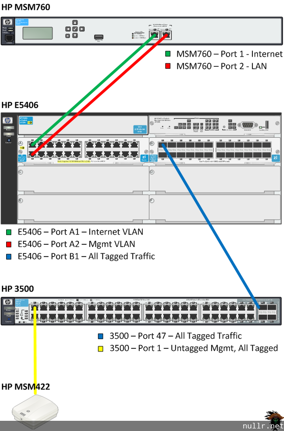
In our example we have an HP E5406 acting as our core router. Connecting to the 5406 we have the HP MSM760 Controller and our edge switch which is an HP3500. Connected directly to the HP3500 we have an HP MSM422 Access Point. Though we only have a single edge switch and single access point, the configuration as covered will expand to cover a fleet of edge switches and access points.
Core
To begin creating our structure we need VLANs. The three VLANs required for this configuration are not unique and likely exist on any mature network.
We’ll start with the Management VLAN. Most enterprise networking devices have either a management IP or specifically designated management port. The Management VLAN is used to house these connections and separate management traffic from regular data traffic. In our case we’ll use this VLAN to allow he MSM Controller to manage the access points. Typically, you would limit the traffic entering the Management VLAN to only IT staff members, we’ll leave it open to the LAN VLAN and lock out the other VLANS.
ip access-list extended "Mgmt-in"
   10 permit ip 172.16.20.0/24 172.16.10.0/24
   20 remark "Allow LAN VLAN traffic to enter Mgmt VLAN"
   30 deny ip any any
   40 remark "Deny all other traffic"
   exit
vlan 10
   name "Mgmt"
   untagged A2
   tagged B1
   ip address 172.16.10.1 255.255.255.0
   ip access-group "Mgmt-in" in
   exit
Next we need our LAN VLAN. This is the typical catch-all VLAN that houses staff member computers. In our case we’ll have both wired and wireless devices living here. Additionally we’ll design an ACL that keeps Public machines out of this VLAN.
ip access-list extended "Deny-Public-in"
   10 deny ip 172.16.30.0/24 any
   20 remark "Deny Public traffic from entering VLAN"
   30 permit ip any any
   40 remark "Permit all other traffic"
   exit
vlan 20
   name "LAN"
   tagged A2,B1
   ip address 172.16.20.1 255.255.255.0
   ip access-group "Deny-Public-in" in
   exit
Lastly we have the Public VLAN for public users. For security we won’t specify a gateway for the Public VLAN, but instead point clients directly to the internet firewall. This will prevent our Core router from allowing inter-LAN communication with the Public VLAN.
vlan 30
   name "Public"
   untagged A1
   tagged B1
   exit
Now to touch on a few piece of the puzzle that fall outside the configuration of the diagram above. As with most environments, the LAN subnet IP addressing is handled by an external DHCP server. For the addressing of the access points, many people will simply put them in the subnet of the public clients and thereby addressing is done by the MSM Controller’s public scope. I prefer to keep the access points on the Management VLAN which helps isolate traffic. Naturally, this adds the complexity of having to create another DHCP scope. In our example we’ll create a DHCP scope on the same DHCP server that addresses the LAN subnet to provide addressing for our Management VLAN. Creation of this separate scope won’t be covered here, but we’re going to assume its in place. Using this assumption we’ll add a helper-address to the Management VLAN pointing to DHCP server on the LAN subnet.
vlan 10
   name "Mgmt"
   untagged A2
   tagged B1
   ip address 172.16.10.1 255.255.255.0
   ip helper-address 172.16.20.10
   ip access-group "Mgmt-in" in
   exit
Key Points:
- Three VLANs
- DHCP scope for LAN and Management supplied by server on LAN
- DHCP scope for Public supplied by MSM Controller
MSM Controller
Before getting underway with the MSM Controller you’ll need to get it on the network. Out of the box the MSM760 is managed from the LAN interface at the IP address 192.168.1.1/255.255.255.0. So source yourself a laptop, set the NIC to 192.168.1.2/255.255.255.0 and connect to port 2 – LAN on the MSM760. Once connected you’ll be taken through some basic setup steps including localization and registration.
IP Interfaces
When the basic setup is completed, we’ll want to re-assign the MSM Controller’s LAN interface to an address on our Management VLAN.
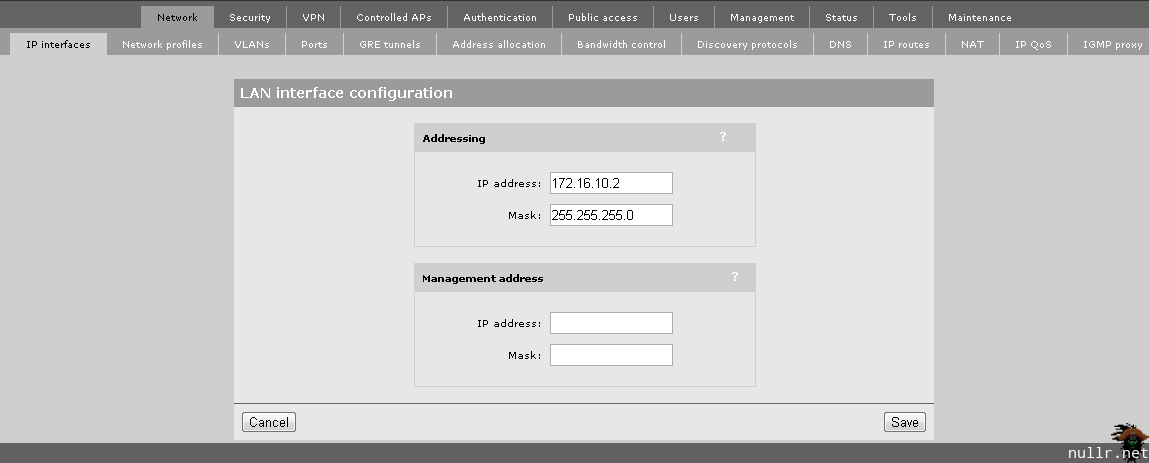
Once you click Save, the MSM Controller will be unreachable. Disconnect your laptop and connect Port 2 – LAN of the MSM760 into port A2 of the 5406. Also connect the Port 1 – Internet port to the 5406 at A1. You should then be able to access the MSM Controller from the web address https://172.16.10.2.
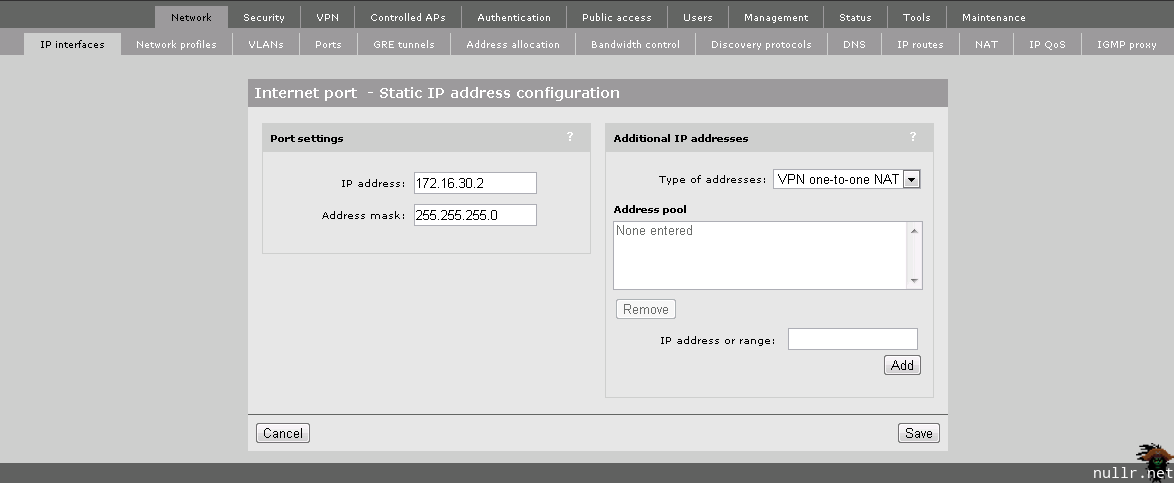
With the LAN port addressing complete, we’ll add the Internet port address as a static IP of 172.16.30.2.

Network Profiles
Now we need to let the MSM Controller know about the existence of the VLANs and where the IP interfaces reside. Under the Network header, we’ll navigate to the Network profile. Using the same configuration as the Core, we add the Management VLAN as VLAN ID 10 and the LAN VLAN as VLAN ID 20.

Once completed, navigate to the VLANs tab and ensure the following are setup:
- LAN Network port is tagged to the LAN port
- Management port is untagged to the LAN port
- Internet port is untagged to the Internet port
Address Allocation
While we’re in the Controller lets create a DHCP scope to offer up leases for Public clients.

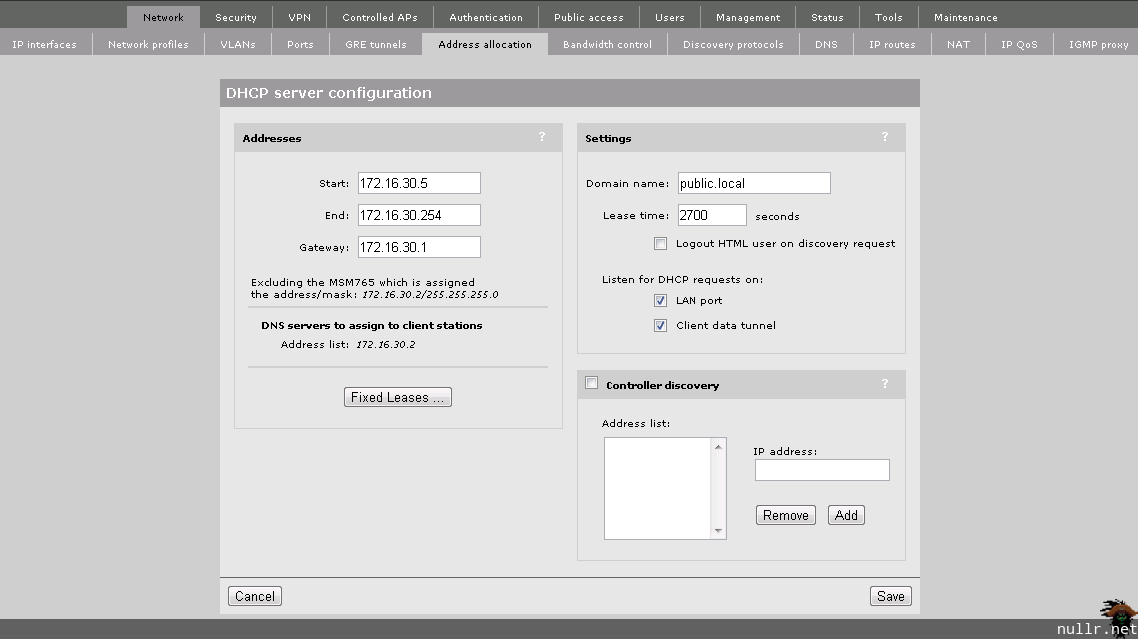
You’ll notice that we’re pointing the Gateway for the Public scope to 172.16.30.1. Where does this come from? The assumption here is that we have an Internet Firewall connected to the 5406 (not shown in the diagram) and it has an interface residing at 172.16.30.1 on the Public VLAN. As mentioned when we created the Public VLAN, this is done for security. The traffic will be routed outside the 5406 and we won’t need to worry about creating ACLs to prevent inter-VLAN communication. Once the networking is accounted for, it’s a good idea to quickly check out the IP Routes section. While we shouldn’t have any special considering at this point, its a good place to look if you’re having connectivity issues later.
Virtual Service Community (VSC)
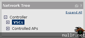
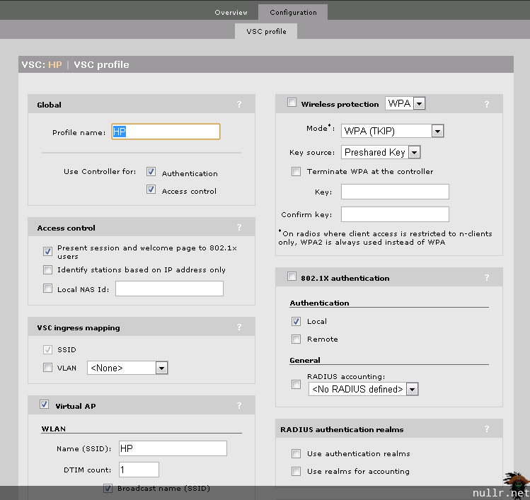
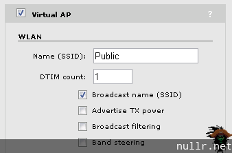
Next we turn our attention to creating the VSCs which define how each wireless network will operate. We’ll be creating two networks (VSCs), one for Staff and the Public. On the Network Tree in the left pane, select the VSCs item and then Add New VSC Profile. First we’ll create the VSC for the Public network.
We won’t cover the VSC in detail as there are a lot of options and at this point the only things we need to worry about is assigning an SSID and Wireless protection (as required).
Once created, complete the same steps for the Staff VSC. Keep in mind that this is for staff and gives access the to the LAN VLAN, so we’ll want to set wireless protection on this one.
Controlled AP Groups
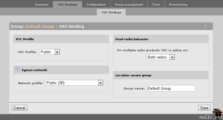
In the Controlled AP Groups section we’ll specify that all Access Points will be permitted to advertize the Staff and Public VSC by setting the Default Group properties. In the Network Tree section of the left pane we’ll expand the Controller APs menu item and select Default Group. Under the VSC bindings section we’ll need to Add New Binding for our Public and VLAN subnets.
Key Points:
- IP Interfaces on each VLAN
- DHCP scope for Public clients
- VSCs are now bound to VLANs
- By default all APs will advertise both Public and Staff SSIDs
Edge
With the Core and MSM Controller configured we turn our attention to the edge switch. We duplicate our Core VLAN configuration and ensure we tag our ports correctly. The key here is to ensure that the access point is untagged on the Management VLAN so it can talk to the MSM Controller and tag the access point to all the other VLANs it carries data for. When a user connects to a specific VSC, the device will be dropped directly onto the bound VLAN, instead of relaying the traffic through the MSM Controller.
vlan 10
   name "Mgmt"
   untagged 1
   tagged 47
   exit
vlan 20
   name "LAN"
   tagged 1,47
   exit
vlan 30
   name "Public"
   tagged 1,47
   exit
MSM Access Point
Finally, we connect the access point to the edge switch. We will connect it to port 1 of the 3500 where it will talk directly with the Management VLAN, but also carries traffic for the LAN and Public VLANs. Keep in mind that unless you’re using external power, you’ll need to use an edge switch with PoE capability.
Once the AP is connected to the port, the following task sequence will start:
- AP will power up with PoE
- AP will broadcast a DHCP request
- DHCP request be caught by 172.16.20.10
- 172.16.20.10 will reply with a Mgmt subnet IP address for the AP
- AP will broadcast a request for an MSM Controller
- MSM Controller will reply with the firmware and configuration information for the AP
- AP will synchronize with MSM Controller and begin advertising Public and Staff SSIDs
Connecting back into the MSM Controller console, you can watch the MSM synchronization process under the Controlled APs section in the left pane. This process can take some time, so be patient.
Key Points:
- Access Point talks to MSM Controller via Management VLAN
- Access Point drops clients onto LAN VLAN directly through LAN VSC
- Access Point sends Public traffic to MSM Controller to be forwarded to public gateway
Wireless Client
With all the pieces in place you’ll be able to connect to the Public and Staff SSIDs as configured in the MSM Controller. Connecting to the Staff SSID will give you a 172.16.20.0/24 address on the LAN VLAN and allow you connect to other devices that VLAN. Connecting to the Public SSID will give you an IP in the range of 172.16.30.0/24 and allow you to connect through the 172.16.30.1 Internet gateway. Additionally, you will not be permitted to access the Mgmt and LAN VLANs from the Public network.
From here’s its easy to go back through the steps above to add additional VSCs bound to VLANs. But first, you’ll also want to go back and look further into VSC configuration. There is a lot of options here including ingress and egressing, bandwidth control, roaming, authentication, QoS, the list goes on. Before going to production spend some time with the HP documentation and get your VSCs dialed in.
