Overview
Today we’ll take a look at the steps required to create a basic security perimeter on a Palo Alto firewall. In particular we’ll be focused on the network segmentation inherent in Palo Alto firewalls and the security and flexibility it imparts. We’ll touch on the three basic deployment methods, but specifically step through a Layer 3 configuration to create a perimeter firewall. As always there are topics we won’t cover in this post, for example we’ll skip right over basic configuration and virtual systems.This post will provide a foundation for later ones that take a deeper dive into the features of the device. Specifically, we’ll build a basic firewall that allows internal hosts to speak to the outside network. We’ll use two interfaces on the Palo Alto, one of which will be connected to our external network the other one to our internal network. Naturally, traffic will need to be NAT’d from the inside to the outside. For the outside network I’ve arbitrarily picked 10.0.0.0/16 and the internal network is 172.16.0.0/16. Sound simple? Good. The steps and screenshots were completed on a PA-3050 running PAN-OS 6.
Deployments
One of the great strengths of the Palo Alto device is the ability to choose from a fairly comprehensive selection of deployments. Ignoring Palo Alto’s ability to create multiple, completely separate, virtual systems you can segment your configurations by choosing one of four different network deployments.
- Virtual Wire – Transparent network segment
- Layer 2 – Switching between two networks
- Layer 3 – Routing between interfaces
In addition to the three methods above there is a fourth deployment option for called Tap mode. Tap mode is not a method by which to provide perimeter security, and as such won’t be included in this post. Keep in mind that picking one deployment method is not to the exclusion of the others. In fact you can deploy any number and combination of deployments with your only limitation being the number of interfaces and required designed. Through the use of network segments and with a choice of the type of inspection, an administrator will quickly find uses for the Palo Alto firewall outside the standard perimeter security device. Let’s take a closer look at each of the methods as well as their benefits.
Virtual Wire
Virtual wire deployments is the simplest of the three. The virtual wire contains no switching and routing information and so by default packets are sent across the wire with no modification. That’s not to say traffic cannot be shaped, as the virtual wire can still allow and deny traffic. One of the great advantages of this method is that it requires no modification of your existing infrastructure. Virtual wire implementations can be put on line and taken off as fast as it takes you to swap cables.
Layer 2
The layer 2 option you’d find most commonly behind an existing firewall, where the interfaces are assigned to VLANs allowing the Palo Alto to pass traffic between them. Once again the device can shape traffic as required using this method.
Layer 3
For the Layer 3 deployment, as expected, traffic is routed between interfaces. This is the most common firewall deployment and probably familiar to most. This is the most powerful of the three as it allows you to take full advantage of the Palo Alto features.
Network
To tackle this configuration we’ll dive into each relevant section of the Palo Alto GUI in turn. For the first part we’ll drill down into the Network section, which as you’d expect contains most of the network configuration. Specifically, we’ll be touching on the following aspects:
- Virtual Routers
- Zones
- Interfaces
Virtual Routers
The first thing we’ll do is configure our Virtual Router. Virtual Routers are much like they sound; they allow you to group interfaces on which routing statements and protocols can be assigned. The advantage here is that there is not just a singular routing table and protocols for the entire device, but a unique set of routing tables and protocols for each virtual router which can be assigned to any number of interfaces. So let’s get started by navigating to Network > Virtual Routers.
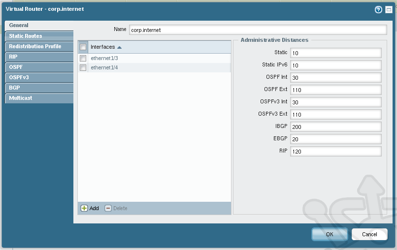
At the bottom of the Virtual Routers window, click on Add. In the new dialog, we’ll name the virtual router corp.internet. Any router needs interfaces so let’s define the interfaces associated with the new virtual router. At the bottom click on Add and select ethernet1/3 from the drop-down. Do the same for ethernet1/4. These will act as the interfaces cabled into our external and internal networks, respectively. If we were using multiple interfaces we could assign the various administrative distances and balance traffic accordingly.
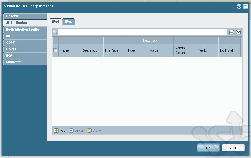
Next let’s add Static Routes. Below the General section click on the Static Routes. At the bottom of the IPv4 tab click Add.
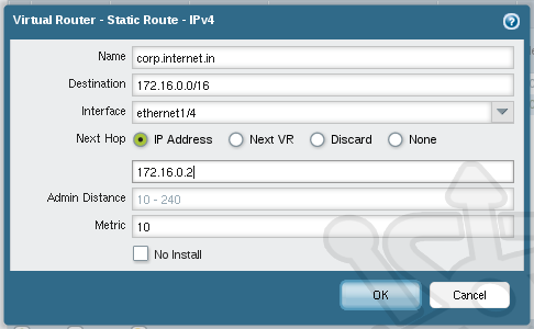
In the Virtual Router – Static Route – IPv4 dialog we’ll add the new gateway for the internal interface. We’ll name the route corp.internet.in and in the Destination field we’ll use 172.16.0.0/16. The Interface will be our internal one, ethernet1/4. For the Next Hop, ensure that IP Address is selected and set the address as 172.16.0.2. Click OK.
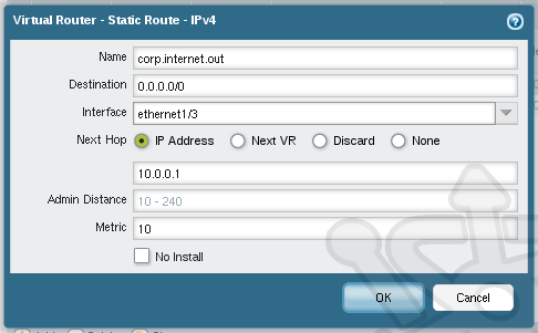
We also need to map a default route for the external interface. Accordingly we’ll name the route corp.internet.out. Set the Destination to 0.0.0.0/0 and the Interface to ethernet1/3. Once again use IP Address and this time we set the gateway as 10.0.0.1.
With the Virtual Router setup complete, your setup should look like the following:
Zones
Zones combine one or more interfaces to be used for traffic to ingress or egress the device. These Zones will be used later to indirectly match our Security Policies to the device Interfaces. By defining zones we’re able to break out of the typical design that has traffic rules assigned directly to interfaces and therefore giving us a much more flexibility. More about security policies and interfaces to follow. Out of the box the Palo Alto devices comes with two predefined zones called Trusted and Untrusted which are utilized by the preconfigured Virtual Wire configuration. Let’s define our own Zones for this Layer-3 configuration. Open Network > Zones.
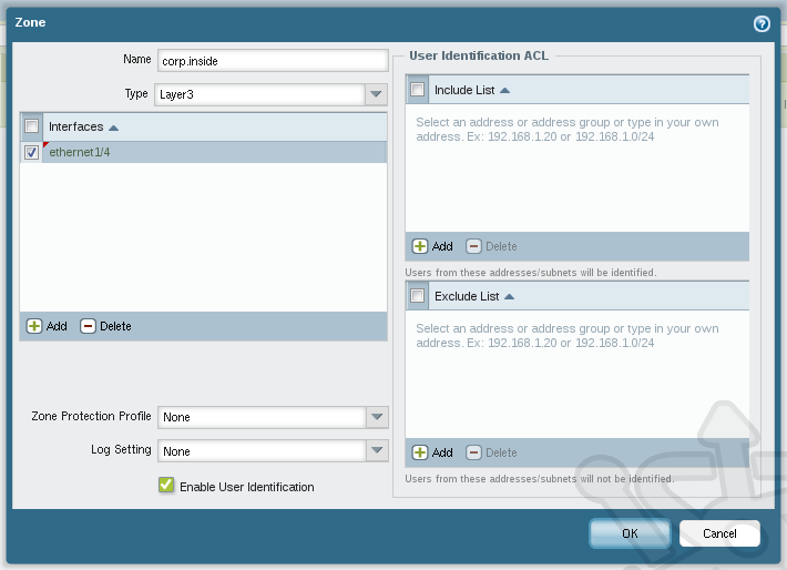
At the bottom of the window click Add. We’ll name this zone corp.inside. Ensure the Type is set as Layer3 and add our inside interface ethernet1/4. If desired we could refine our traffic further by using the include and exclude lists with an appropriate access control list. The Enable User Identification feature, if configured, enables Palo Alto’s User-ID for this Zone. Lastly, Zone Protection can provide an extra level defense against floods, port scans and packet level attacks. Click OK.
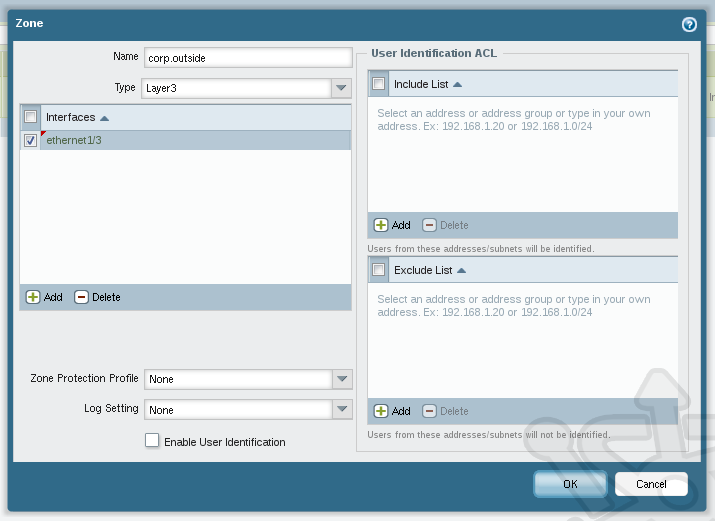
Let’s create another zone to represent the outside. The name will be corp.outside which will be a Layer3 zone with the outside interface ethernet1/3.
Our Zone configuration should look like this:
Interfaces
In the Interfaces section we are able bind the Virtual Router and Security Zones together with specific interfaces. Navigate to Network > Interfaces.
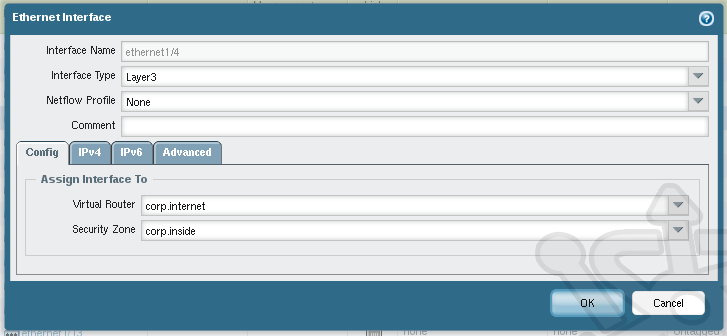
Next click on ethernet1/4 and set the Interface Type to Layer 3. Set the Virtual Router to our corp.internet we created earlier and assign corp.inside as the Security Zone.
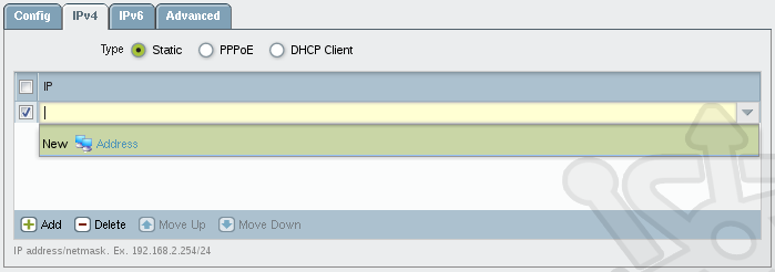
With the Virtual Router and Security Zone assigned, we need to add an IP address to this interface. To make for easier modification down the road we’ll create an address object. Under the IPv4 tab, click Add and then click Address from the drop-down.
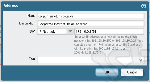
In the Address dialog we’ll name the new address object corp.internet.inside.addr. Set the Type to IP Netmask with an address/mask of 172.16.0.1/24. Additionally you can create tags to easily locate devices once you have a large collection.
With the object created, we should now see the newly created object under the IP header. Click OK.
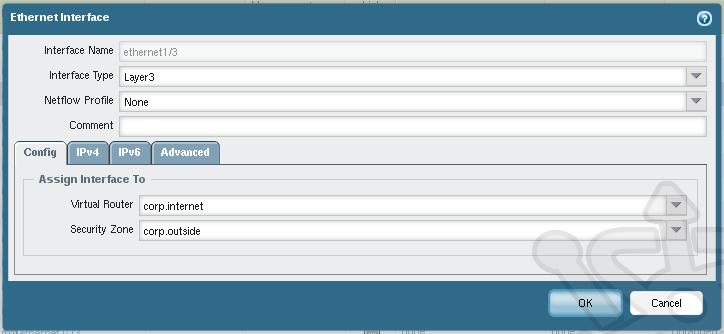
Back in the interface list locate we’ll next open ethernet1/3, this will be our external interface. Set the Interface Type to Layer 3. In the Config and assign Virtual Router to corp.internet and Security Zone to corp.outside
On the IPv4 tab, ensure Static is selected and click Add. Once again, we’ll create an address object. This time we’ll call it corp.internet.outside.addr with an address of 10.0.0.2/24
In the interface list we should see the new object addresses with the virtual routers and security zones next to our internal and external interfaces. Also notice the preconfigured Virtual Wire interfaces on ethernet1/1 and ethernet1/2.
Policies
Simply put, a Policy defines how traffic is treated. As a minimum the two policies we require are NAT and Security Policies. The NAT policy allows traffic to be translated from the internal to external network, as you’d expect from NAT. For our purposes it’d be fair to say that security policies enable us to allow and block traffic, but the flexibility of these rule go well beyond. Through Palo Alto’s App-ID feature you can identify an application that you’re interested in and what should be done with the traffic without having to know how the traffic looks or behaves. Security Policies can also leverage the User-ID feature mentioned earlier to give granularity of traffic control based on the user requesting it, but these are topics for another day.
NAT Policy
Our first stop in the policies section will be to configure our NAT. In here we’ll bind together source and destination zones with the address to be translated. Let’s navigate to Policies > NAT.
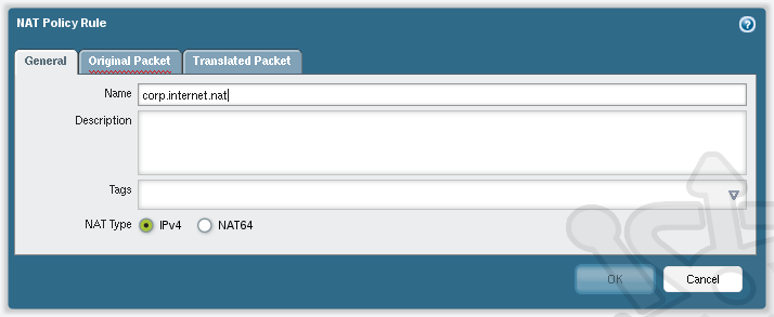
At the bottom of the dialog click Add, which will open a NAT Policy Rule window. We’re going to name the new policy corp.internet.nat.
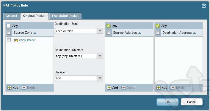
Next click on the Original Packet tab where we’ll define the path of our traffic. Under the Source Zone section on the left, click Add and select our corp.inside zone to indicate the source of our traffic. In the middle section under Destination Zone we’ll select the corp.outside zone. Since our corp.outside zone is assigned to a single interface (ethernet1/3) you can leave the Destination Interface as any.
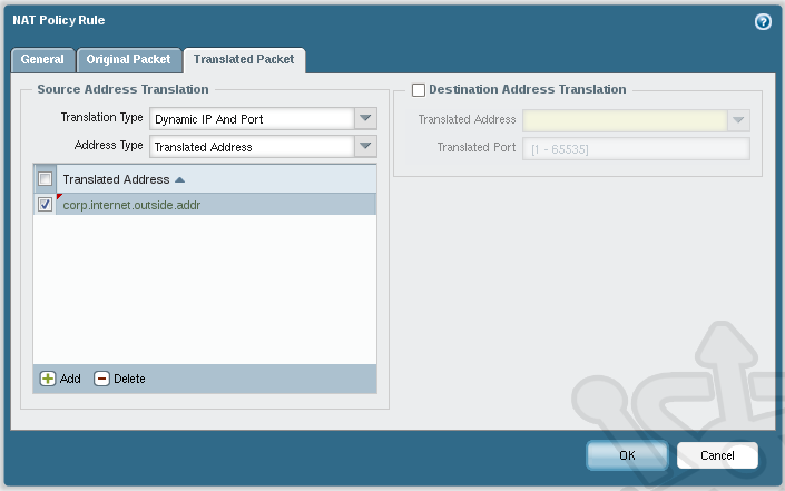
Lastly, under the Translated Packet tab set the Translated Type to Dynamic IP And Port, as well set Address Type to Translated Address. We then add the corp.internet.outside.addr object as the Translated Address. Once complete, click OK.
In the NAT list we should see our newly created NAT statement.
PAN-OS 5 – NAT
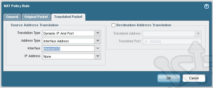
If you’re completing these steps on version 5 of the OS-PAN, be sure to pay attention to the NAT logic. In the Translated Packet tab set the Interface drop-down to the *external* interface. Its easy to mistakenly set the interface to internal as the section is called Source Address Translation. We’ve already defined the source in the Original Packet tab, we need to specify the interface (therefore the IP address) the internal traffic need to be NAT’d to.
Security Policy
Last, but not least we need to define our Security Policy. As mentioned this is the means by which we allow or block the flow of traffic. At this point we’re just interested in the allowing the flow of traffic from our internal zone to the external zone, so the policy will be fairly simple. Navigate to Policies > Security.
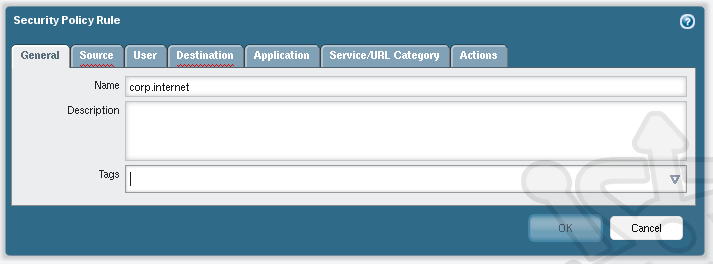
At the bottom of the Security section click Add to create a new policy. In the Security Policy Rule window we’ll name the rule corp.internet.
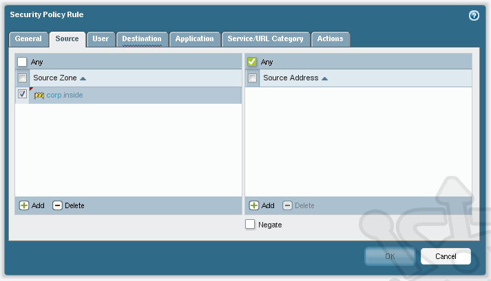
Click on the Source tab and add corp.inside as the Source Zone.
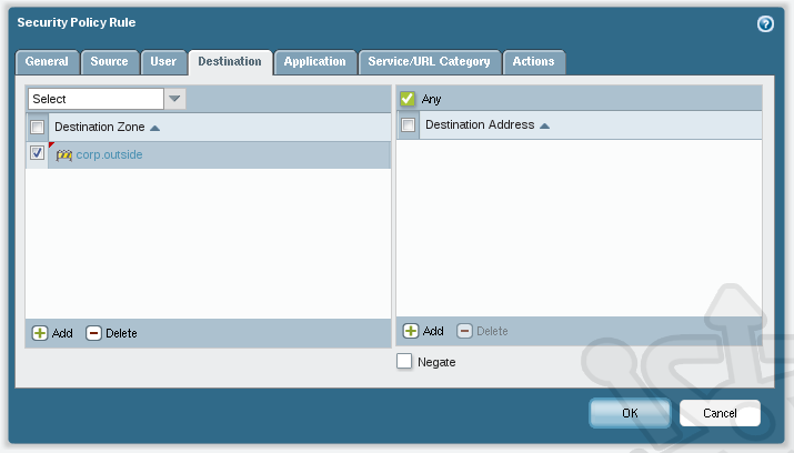
Next on the Destination tab, add corp.outside as our Destination Zone.
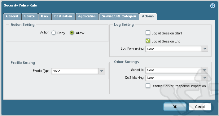
Under the Actions tab ensure the Action is set to Allow and click OK to complete.
In the Security Policy list ensure that our newly created rule matches below.
Verification
With this in place, let’s run a simple test against our security rule and ensure it’s correct.
admin@PA-3050> test security-policy-match source 172.16.0.10 destination 10.0.0.10 destination-port 80 protocol 6

corp.internet {
from corp.inside;

source any;
source-region none;
to corp.outside;
destination any;
destination-region none;
user any;
category any;
application/service  any/any/any/any;

action allow;
terminal yes;
}

admin@PA-3050>
That concludes the perimeter firewall configuration on a Palo Alto allowing traffic from our internal network to be NAT’d externally. As mentioned this post is meant to lay the ground work for future posts where we’ll take a closer look at some of the unique features of this device.








Hi Can the Verfication be done Via the GUI (like cisco ASA Packet tracer) or can it only be done via command line ?
As of the current release the ‘test’ tool is only available through the command line.
Hi, Can Palo-Alto manage Layer2 and layer 3 for the same VLAN domain i.e VLAN100? Or Can we assign/use a same vlan to the virtual-wire and layer 3 routed interface?
Hello Shayaan – Palo Alto requires each interface be assigned a type, so each interface must choose between Virtual Wire, Layer 2 and Layer 3 (etc). If you’re specifically configuring the device to have knowledge of VLANs, then the interface would need to be assigned as a Layer 2 type. You can however have multiple interfaces of different types living on a single VLAN. So if you wanted, you could have a Virtual Wire and Layer 3 interface both on VLAN100, or likewise a Layer 2 and Layer 3 interface. I hope this answers your question.
Thanks Drew.